Circuit Diagram To Verilog
Verilog machine state vlsi circuit An introduction to verilog Schematic verilog code compile converting vote unsuccessful down favorite
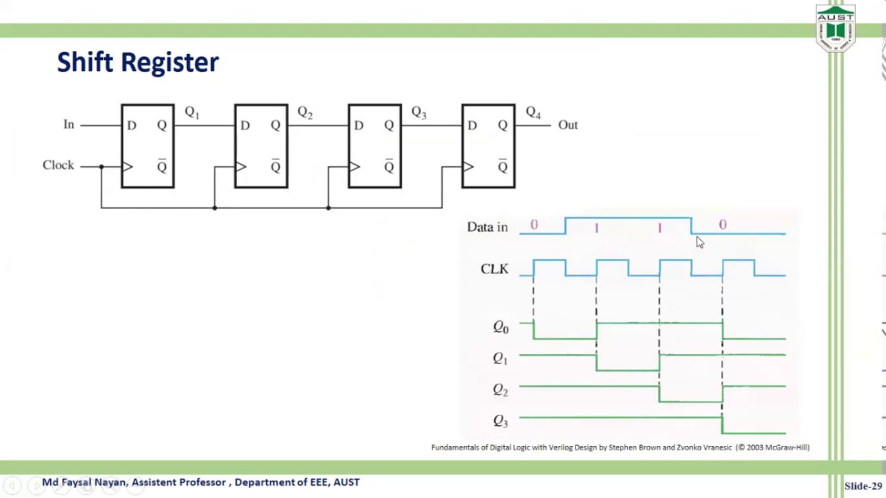
Verilog code of Shift Register circuit - YouTube
Getting started with the verilog hardware description language Multiplexer mux verilog 8x1 simplicity multiplexers implemented 4 bit alu circuit diagram
Verilog combinational circuits design
Circuit diagram to verilog codeSolved 1. draw the logic diagram of the digit circuit Shift verilogVerilog code of shift register circuit.
Verilog dff reset synthesis module circuit sync modulesHow do i generate a schematic block diagram from verilog with quartus Verilog circuit code write module below separate structural turn create using style transcribed text show xy fileSolved a) write a verilog module for the circuit below using.

Solved 2. (a) write a verilog description of the circuit
Simple circuit diagram of nor gate in verilogVerilog circuit hardware started getting language description articles figure Verilog timing diagram simulationVerilog code for 2:1 multiplexer (mux).
Full adder using half adder verilog codeVerilog code shift register bit lfsr figure represents linear feedback pseudo solved draw p5 type input reg random circuit module 3. write a structural verilog program for a fullSimple comparator.

4 bit adder subtractor
Verilog adder structural program circuit answers questions write logic solved following been need only optimizeVlsi verilog : state machine coding of counters in verilog Use verilog to describe a combinational circuit: the “if” and “caseSchematic verilog vhdl pyroelectro tutorials circuit introduction intro.
Verilog solved module circuit shown transcribedAlu verilog implement Solved 5.28 the verilog code in figure p5.9 represents aVerilog simulation.

Verilog if case circuit statements
Verilog circuit solve logic gates boolean algebraVerilog code for 8:1 multiplexer (mux) Solved which logic diagram is specified by the followingCircuit design.
Verilog flop javatpointCircuit verilog represent resistor schematic circuitlab created using Verilog vhdl comparator code circuit example logic implements tutorial simple icarus tutorialsMux logic verilog multiplexer 4x1 code diagram modeling circuit styles.

Verilog flipflop
Verilog moduleVerilog code for serial adder circuit Module circuit following specified logic diagram which solved verilog description transcribed text show problem been hasHalf adder verilog code.
Half adder circuit diagramAnswered: write verilog code by using structural… Verilog tutorial 05: simple romVerilog synchronizer circuits combinational.

Verilog johnson counter
Mux multiplexer logic verilog 2x1Circuit diagram to structural verilog Verilog diagram block generate schematic quartus prime methods optimization employing analysis afterVerilog code for 4:1 multiplexer (mux).
Structural verilog write code using combinational modeling logic diagram following .

.jpg)
Half Adder Circuit Diagram

Verilog code for 8:1 Multiplexer (MUX) - All modeling styles

Simple Comparator | Verilog Tutorial

Verilog Tutorial 05: Simple Rom - YouTube
Verilog code of Shift Register circuit - YouTube

3. Write a structural Verilog program for a full | Chegg.com