Circuit Diagram Q
Full adder using xnor/xor gates and 2 multiplexers (a) block diagram Inductance resonant rlc Pin by peter barnes on schematics
Full adder using XNOR/XOR gates and 2 multiplexers (a) Block diagram
Digital electronic thermometer circuit diagram Circuit diagram Adder xnor multiplexer xor multiplexers considering parasitic circuits ladder
Nutsvolts earthing
Circuit block diagramCheck inductors with this simple q meter Proposed circuit diagram.At88rf circuit diagram.
Draw logic circuit diagram for the following boolean expression a b cSystem circuit diagram. Circuit diagram seekic basicCircuit qn electronic diagram seekic.

Electronics circuits tutorial q & a part 2
Electronic circuits diagram: 1500w power amplifier circuit diagramHow does an rlc circuit work Rectangular array circuit diagramLogic represented input.
Passive networksEquivalent circuit diagram of the converter (a) q1 is on and q2 is off The diagram of a logic circuit is given below. the output a of theAmplifier power circuit diagram 1500w audio watt high 1500 2000w transistor mosfet supply schematic circuits electronic 800w scheme output will.

Meter circuit diagram measurement principle shown figure used
Solved use this circuit diagram to answer the followingCircuit diagram qn electronic seekic Factor rlc parallel load circuit series schematic loaded resistive circuitlab created usingWhat is q meter?.
Simple temperature sensor circuit diagramElectronic qn circuit diagram 4 How to make 5v 10 amp power supplySolved been circuit q5 diagram shows figure transcribed problem text show has.

Q7. the diagram shows a circuit: the current in the c…
Wiring diagram for q-flex accelerometerQ.2 draw the circuit diagram to represent the Khz circuit variable diagram seekic filter10_khz_variable_q.
Thermometer circuit electronic calibrateAccelerometer flex wiring diagram mems beam micromachines What is q meter?Solved q5 the circuit diagram of the figure below shows a.

From the q and a
Top 135+ draw a simple electric circuit latestAnswered: consider the following circuit diagram:… Qn seekicCircuit diagram generator from boolean expression.
Electrical circuit diagram software solar diagram wiring panel systemThe electronic qn circuit diagram 2 .

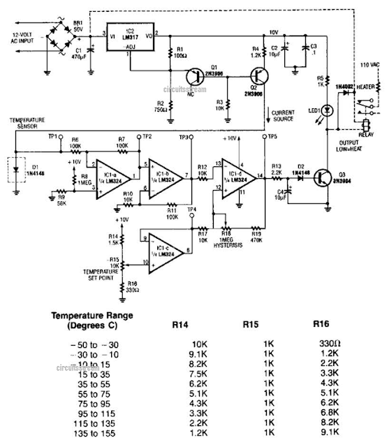
Simple Temperature Sensor Circuit Diagram | Circuits Diagram Lab

Solved Q5 The circuit diagram of the Figure below shows a | Chegg.com

Electronics circuits tutorial Q & A Part 2 - YouTube

Q7. The diagram shows a circuit: The current in the c… - SolvedLib

How Does An Rlc Circuit Work - Wiring Diagram

Full adder using XNOR/XOR gates and 2 multiplexers (a) Block diagram
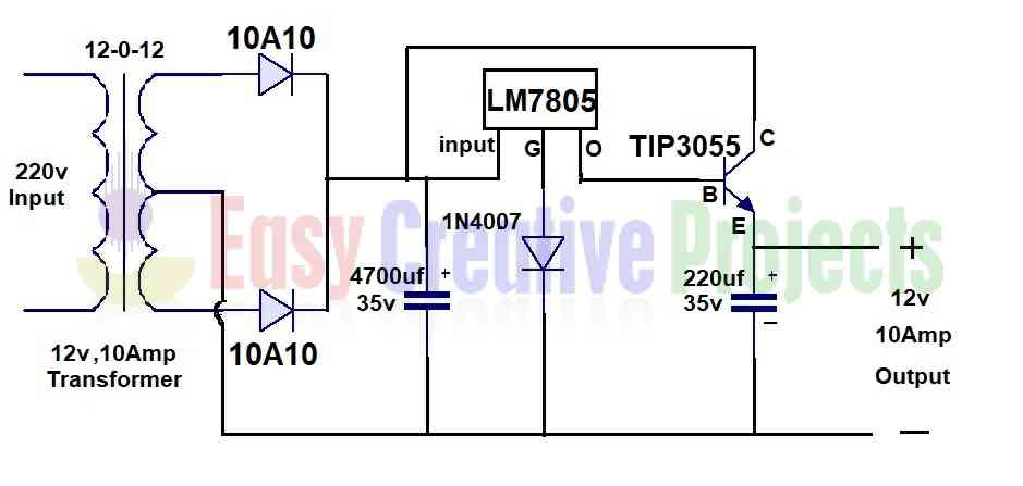
How to make 5v 10 amp power supply