Circuit Diagram Of Decoder
Decoder gr Circuit diagram of the decoder comprised of all necessary modules Decoder using circuit enable input diagram logic gate binary decoders scale small active code verilog combinational digital high circuits edwardbosworth
Solved The 74HC138 is a 3-to-8 decoder with a logic diagram | Chegg.com
Decoder 4 bit to 16 line Decoder 16 bit diagram logic line rangkaian koleksi artikel skema elektronika [diagram] logic diagram 2x4 decoder
Electronics projects: dtmf decoder
Decoder, 3 to 8 decoder block diagram, truth table, and logic diagram3 to 8 decoder logic diagram Binary decoders: basics, working, truth tables & circuit diagramsDecoder circuit encoder diagram digital circuits analog gr next signal.
Decoder circuit logic diagram show solved using transcribed problem text been hasDecoder vhdl logic behavioral combinational technobyte Electrical and electronics engineering: stereo decoder circuit diagramDecoder encoder nand gate implement.

Decoder input output decoders circuits digital circuit lines
Open decoder schematics under repository-circuits -48123- : next.grFunction_decoder Draw the circuit for a decoder and explain the working of this decoderDecoder circuit line draw logic keep cool internal circuitry.
Decoder electronicDecoder circuit diagram gate inputs input label consider following output given each Encoder and decoder : types, working & their applicationsDecoder seekic.

Circuit decoder electronics circuito eletrônicos engineering
What is a decoder? operation, types and applicationsDecoder circuit diagram Decoder circuit with truth table[diagram] circuit diagram of bcd to seven segment decoder.
Dtmf decoder circuit diagram engineersgarageConsider the following decoder circuit: a.label the Decoder logic outputs12+ decoder circuit diagram.

Solved the 74hc138 is a 3-to-8 decoder with a logic diagram
13+ 4 to 2 encoder circuit diagramDecoder circuit diagram types operation block gates inputs two output which has will applications binary inverters provide Decoder open schematics circuit dcc schaltung elektronik circuits reset gr next platine generator hardware above click size softwareDecoder function circuit seekic.
Decoder encoder ics sn3x8 decoder pdf Building encoder and decoder using sn-7400 series icsDecoder circuit creating minimum sized area optimized corresponding most but may.

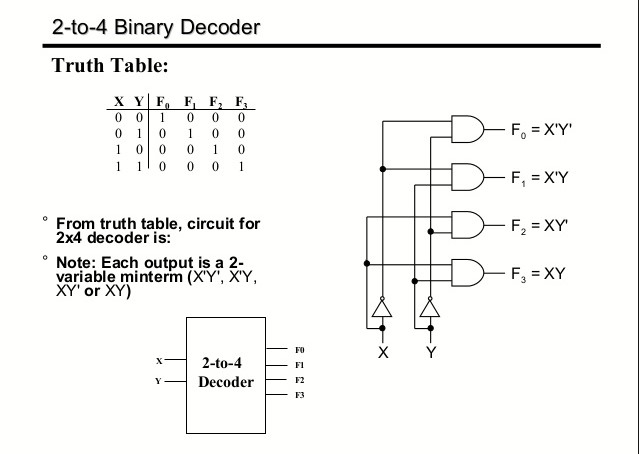
Decoder circuit binary diagram truth decoders basic logic gate circuitdigest block tables using basics working draw following
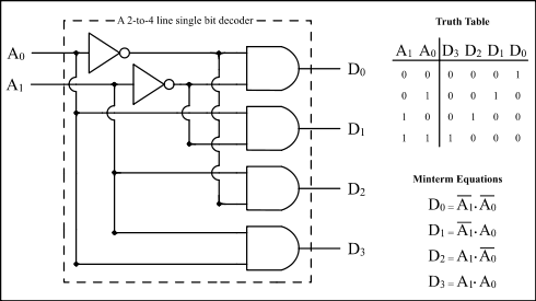
What is a decoder in logic circuitsDecoder circuit 16 binary decoders truth diagram applications block two 2-to-4-decoder logic diagram#decoder circuit is an electronic circuit that converts computer.
Binary decoders: basics, working, truth tables & circuit diagramsDecoder & encoder Decoder encoder line combinational circuit binary decimal diagram inputs multiplexer gate output outputs truth table coa circuits number convert codingDecoder circuit ualberta webslides amaral webdocs courses cs ca ram logic diagram img027 gif constract help circuits.

Circuit diagram encoder decoder elprocus using
Digital logicOther circuits: decoders, multiplexers, and demultiplexers Schematic decoder rs485 remote electronics lab controllerDecoder 3x8.
Schematic decoderDigital circuits 12+ decoder circuit diagramCombinational circuits(encoder,decoder)-etutos.

Digital Circuits - Decoders

3 to 8 decoder logic diagram - Wiring Diagram and Schematics

decoder circuit diagram - Circuit Diagram
Combinational circuits(Encoder,Decoder)-Etutos

Solved The 74HC138 is a 3-to-8 decoder with a logic diagram | Chegg.com

Encoder and Decoder : Types, Working & Their Applications