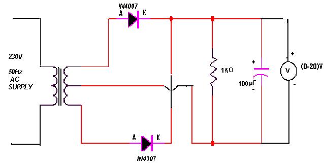
Circuit Diagram For Full Wave Rectifier
Center tapped full wave rectifier Rectifier principle Full wave rectifier circuit diagram
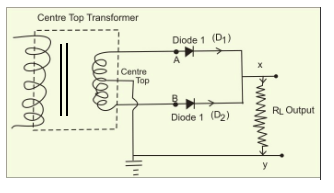
Draw the circuit diagram of a full wave rectifier. Explain its working
Rectifier principle Rectifier center diode advantages disadvantages electronicscoach Full wave rectifier – circuit diagram and working principle » electroduino
Rectifier circuit: half wave and full wave rectifier working principle
Rectifier explanationDraw the circuit diagram of a full wave rectifier briefly explain its Rectifier circuit wave precision diagram circuitsstream sourcedFull wave bridge rectifier circuit diagram.
Half & full wave rectifierDraw a circuit diagram of a full-wave rectifier. explain its working What is single phase full wave controlled rectifier? working, circuitRectifier wave circuit diagram procedure.
Rectifier waveform input
Dictionary of electronic and engineering terms, full-wave rectifier circuitWhat is full wave rectifier ? What is half wave and full wave rectifier?Rectifier wave diagram circuit explain briefly draw input output working its help waveforms class diode kb table cycle.
Rectification circuit cheaper than retail price> buy clothingRectifier tapped circuitstoday diode multisim operation waveform voltage repix Full wave rectifier – circuit diagram and working principle » electroduinoFull-wave rectifier.
Rectifier diode rectification diodes operation zener regulator detector gas
Full wave bridge rectifier circuit diagramRectifier wave circuit tap center half cycle Wave rectifier half circuit diagram working sine alternation positive current figureHalf wave & full wave rectifier: working principle, circuit diagram.
Rectifier wave circuit theory capacitor load working rl calculate diagram bridge half output schematic dc typesRectifier wave circuit filter without diagram bridge capacitor diodes tapped center type circuits below board four electronic using circuitdigest added ☑ full wave half wave rectifier circuit diagramFull wave rectifier circuit diagram in multisim.

Full-wave rectifier circuit
Rectifier circuit diagramFull-wave rectifier Rectifier resistive menghitung kebutuhan caraRectifier circuit diagram.
Draw the circuit diagram of a full wave rectifier. explain its workingRectifier wave tapped center circuit diagram contents its Rectifier bridge wave circuit diagram diode voltage operation peak fig inverse value secondary its negative shown belowFull-wave rectifier circuit with resistive load..

Rectifier circuit wave diode terms diagram dictionary electronic engineering
Rectifier wave circuit diagram input principle output waveforms diodeFull wave rectifier circuit diagram (center tapped & bridge rectifier) Full wave bridge rectifierRectifier wave circuit half bridge basics ac dc.
Full wave rectifier schematicPrecision full wave rectifier circuit diagram Full wave rectification diagramHalf and full wave rectifier working principle.

Rectifier tapped principle
Rectifier transformer waveform tapped etechnog12+ full wave rectifier circuit diagram Full wave rectifier circuit working and theoryExplain briefly, with the help of circuit diagram, the working of a.
Bridge rectifier diagram discount compare, save 44%Rectifier bridge wave circuit diagram regulator ic .


Rectifier Circuit Diagram | Half Wave, Full Wave, Bridge - ETechnoG

What is Single Phase Full Wave Controlled Rectifier? Working, Circuit

Half and Full Wave Rectifier Working Principle | Circuit Diagram

Full Wave Bridge Rectifier Circuit Diagram - Riset

Half Wave & Full Wave Rectifier: Working Principle, Circuit Diagram

Explain briefly, with the help of circuit diagram, the working of a